GMS:Output Control
From XMS Wiki
(Redirected from GMS:MODFLOW Global Output File)
Jump to navigationJump to search
| MODFLOW | |
|---|---|
| Pre-processing | |
| MODFLOW Commands | |
| Building a MODFLOW Model | |
| Map to MODFLOW | |
| Calibration | |
| Packages Supported in GMS | |
| Saving a MODFLOW Simulation | |
| Importing MODFLOW Files | |
| Unsupported MODFLOW Features | |
| Run MODFLOW | |
| Post-processing | |
| MODFLOW Display Options | |
| MODFLOW Post-Processing Viewing Options | |
| Reading a MODFLOW Simulation | |
| Tutorials | |
| Packages | |
| Flow: | BCF6, HUF, LPF, UPW |
| Solvers: | SMS |
| Other: | UZF1 |
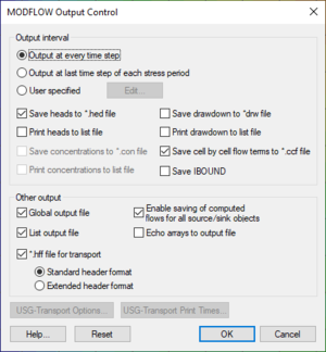
The Output Control dialog is accessed from the MODFLOW menu. The Output Control dialog contains the following options:
Output Interval Options
The Output Interval section allows choosing which files to output and when to output the results. By default, GMS instructs MODFLOW to output heads and volume data to both data files and text output files. Drawdown is not output by default.
Other Output Options
- Global Output File
- Choose this option to use the global output file (*.glo). This file contains information about the input files and, during an inverse run using the PES process, will contain information about each iteration. Either the global file, list file, or both must be used with MODFLOW.
- List Output File
- Choose this option to use the list output file (*.out). This file contains information about the current MODFLOW run. This file will be overwritten during an inverse run using the PES process for each inverse iteration.
- *.hff File For Transport
- Select this option to output the head and flow file (*.hff) used by MT3DMS to generate the flow fields for transport modeling.
- Enable saving of computed flows for all source/sink objects
- This option allows GMS to create a flow observation for all sources/sinks that were created using the Map→MODFLOW command so that the user can see the computed flux through the group of boundary conditions. If the user is doing a transient simulation then having this option may cause MODFLOW to crash because MODFLOW attempts to allocate more memory than any of us have available. Turning off this option in this situation is the best course of action.
MODFLOW-USG Transport Options
When using MODFLOW-USG Transport, the following options are available:
- USG-Transport Options – This button will bring up the USG-TRANSPORT Options dialog. This dialog has the following options:
- Use adaptive time stepping (ATSA) – Option to turn off or on adaptive time stepping. Select "Yes" to turn on.
- Number of print times (NPTIMES) – Specify the number of prints times if using adaptive time stepping. The print times can be entered using the USG-Transport Print Times button in the MODFLOW Output Control dialog.
- Number of output steps (NPSTEPS) – Enter the number of steps after which output is provided. When adaptive time stepping is used, the output control items that are otherwise provided for every time step are instead provided for every stress period.
- Hot start stress period (ISPFAST) – Enter a value for the stress period number to which to fast-forward.
- Hot start time step (ITSFAST) – Enter a value for the time step number of ISPFAST value to which to fast-forward.
- USG-Transport Print Times – This button open a Table dialog where the print times can be entered. The number of entries in the table are set by the Number of print times (NPTIMES) option in the USG-TRANSPORT Options dialog.
| GMS – Groundwater Modeling System | ||
|---|---|---|
| Modules: | 2D Grid • 2D Mesh • 2D Scatter Point • 3D Grid • 3D Mesh • 3D Scatter Point • Boreholes • GIS • Map • Solid • TINs • UGrids | |
| Models: | FEFLOW • FEMWATER • HydroGeoSphere • MODAEM • MODFLOW • MODPATH • mod-PATH3DU • MT3DMS • MT3D-USGS • PEST • PHT3D • RT3D • SEAM3D • SEAWAT • SEEP2D • T-PROGS • ZONEBUDGET | |
| Aquaveo | ||
