GMS:HFB Package
| MODFLOW | |
|---|---|
| Pre-processing | |
| MODFLOW Commands | |
| Building a MODFLOW Model | |
| Map to MODFLOW | |
| Calibration | |
| Packages Supported in GMS | |
| Saving a MODFLOW Simulation | |
| Importing MODFLOW Files | |
| Unsupported MODFLOW Features | |
| Run MODFLOW | |
| Post-processing | |
| MODFLOW Display Options | |
| MODFLOW Post-Processing Viewing Options | |
| Reading a MODFLOW Simulation | |
| Tutorials | |
| Packages | |
| Flow: | BCF6, HUF, LPF, UPW |
| Solvers: | SMS |
| Other: | UZF1 |
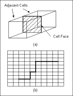
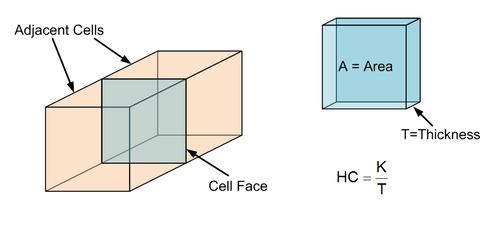
The Horizontal Flow Barrier (HFB) package is used to simulate the effect of sheet pile walls, slurry trenches, or other objects which act as a barrier (or partial barrier) to horizontal flow. Barriers are simulated in the HFB package by identifying cell boundaries which approximately coincide with the location of the barrier and assigning a hydraulic characteristic to each cell boundary. Each cell boundary represents a vertical face between two adjacent cells as shown in the following figure.
Contents
Hydraulic Characteristic
The original version of the HFB package required the input of the hydraulic characteristic either as barrier transmissivity divided by the width of the horizontal-flow barrier (for layer types 0 and 2 in BCF) or as barrier hydraulic conductivity divided by the width of the horizontal-flow barrier (for layer types 1 and 3 in BCF). In the current HFB package, the hydraulic characteristic is always the barrier hydraulic conductivity divided by the width of the barrier, regardless of the layer type or flow package (BCF or LPF) used; thus, layer thickness is always used in calculating the contribution to the conductance terms. The HFB package uses cell elevations specified in the discretization file to calculate cell thickness. Cell thickness is head dependent for layer types 1 and 3 in the BCF package and for convertible layers in the Layer-Property Flow package. (taken from MODFLOW 2000 documentation)
Defining Barriers
Barriers are defined in one of two ways: (1) they can be defined using a set of arcs in the Map module or (2) they can be defined one cell boundary at a time using the Toggle Barrier command in the 3D grid module.
Using the Map Module
In most cases, the simplest method is to create one or more Horizontal Flow Barrier arcs in the Map module corresponding to the barriers and let GMS automatically find the closest sequence of cell boundaries and mark them as barriers.
Using the Toggle Barrier Command
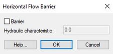
Horizontal flow barriers can also be defined one at a time by selecting two adjacent cells and selecting the MODFLOW | Advanced| Toggle Barrier menu command. This brings up a dialog that can be used to mark the boundary between the two selected cells as a barrier and to enter a hydraulic characteristic for the barrier. This same command can be used to delete a barrier between two cells.
HFB Package Dialog
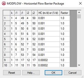
Regardless of which method is used to define the barriers, an existing set of barriers can be viewed and edited using the HFB Package command in the MODFLOW menu. This command brings up the MODFLOW – Horizontal Flow Barrier Package dialog. This dialog can be used to edit the location and hydraulic characteristic of each of the currently defined barriers.
Spreadsheet
For cells where horizontal flow barriers have been assigned, the hydraulic characteristic assigned to each cell is displayed in the spreadsheet portion at the lower part of the dialog.
Reset
The Reset button can be used to delete all barriers.
| GMS – Groundwater Modeling System | ||
|---|---|---|
| Modules: | 2D Grid • 2D Mesh • 2D Scatter Point • 3D Grid • 3D Mesh • 3D Scatter Point • Boreholes • GIS • Map • Solid • TINs • UGrids | |
| Models: | FEFLOW • FEMWATER • HydroGeoSphere • MODAEM • MODFLOW • MODPATH • mod-PATH3DU • MT3DMS • MT3D-USGS • PEST • PHT3D • RT3D • SEAM3D • SEAWAT • SEEP2D • T-PROGS • ZONEBUDGET | |
| Aquaveo | ||


