GMS:MNW2 Package
| MODFLOW | |
|---|---|
| Pre-processing | |
| MODFLOW Commands | |
| Building a MODFLOW Model | |
| Map to MODFLOW | |
| Calibration | |
| Packages Supported in GMS | |
| Saving a MODFLOW Simulation | |
| Importing MODFLOW Files | |
| Unsupported MODFLOW Features | |
| Run MODFLOW | |
| Post-processing | |
| MODFLOW Display Options | |
| MODFLOW Post-Processing Viewing Options | |
| Reading a MODFLOW Simulation | |
| Tutorials | |
| Packages | |
| Flow: | BCF6, HUF, LPF, UPW |
| Solvers: | SMS |
| Other: | UZF1 |
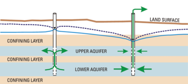
The Multi-Node Well (MNW2) package is an updated revision of the MNW package meant to replace the MNW1 package. It includes modifications to better model partially penetrating wells, non-vertical wells, and includes the ability to specify a pump performance curve. The MNW package was developed to more accurately model wells spanning multiple aquifers or in a single heterogeneous aquifer, partially penetrating wells, and horizontal wells that can be affected by the effects of dynamic changes in the distribution of pumping or intraborehole flow that can significantly alter groundwater flow. A MODFLOW model can not use both the MNW1 and MNW2 packages, it must use one or the other. A detailed description of the MNW2 input is available at the USGS website.
MNW2 boundary conditions can be directly added via the Multi-Node Well (MNW2) package dialog. Boundary conditions can also be added to selected cells using the Point Sources/Sinks command in the MODFLOW menu. For a conceptual model MNW2 points can be defined in the map module.

Contents
Conceptual Model
An MNW2 well can be added to a conceptual model by creating an MNW2 point. The geometry of the well screen can be set using the Use screen attribute for a single screen, or for multiple screens the geometry can be set using the Boreline attribute button. If niether one is set, the generated well nodes include the grid layers specified for the coverage by its default layer range.
Multi-Node Well (MNW2) Package Dialog
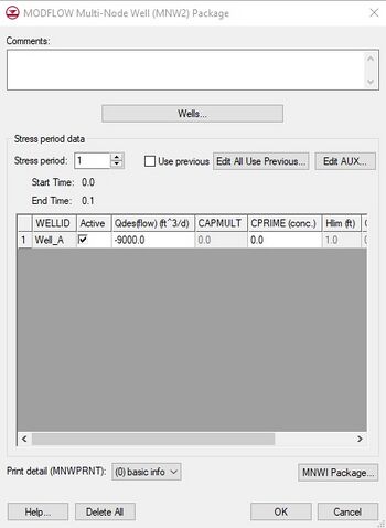
MNW2 wells can be edited in the Multi-Node Well (MNW2) Package dialog. The main dialog allows editing stress period data for wells. The stress period field shows the current stress period and allows you to cycle through stress periods and view the well properties for each stress period in the spreadsheet below. MNW2 AUX fields can be added and removed by clicking on the Edit AUX... button. The values are displayed in the spreadsheet. Controls to edit the print detail (MNWPRNT) and the MNWI package values are available below the spreadsheet. Wells can be added, edited and removed by clicking on the Wells... button to bring up the MNW2 Wells dialog.
MNW2 Wells Dialog
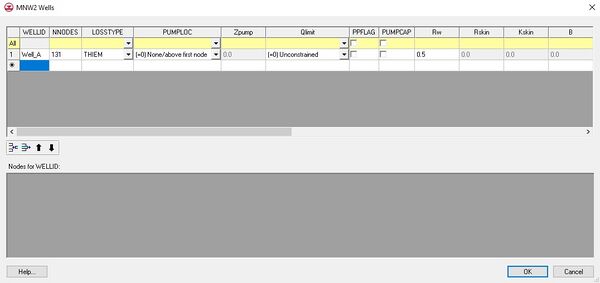
The MNW2 Wells dialog allows wells to be added, removed, and edited. It consists of two spreadsheets. The top spreadsheet lists the table of MNW2 wells. When a well in the top spreadsheet is clicked on, the nodes for the well are listed in the bottom spreadsheet. Nodes can be added and removed by changing the NNODES column in the wells spreadsheet.
Sources/Sinks Dialog
An MNW2 well can be added or edited for a selected cell using the Sources/Sinks menu item under the MODFLOW menu. The well info can be edited from the Sources/Sinks dialog by clicking on the ![]() button in the Edit column.
button in the Edit column.
Notes
- ^ Konikow, Leonard F. (2009), Revised multi-node well (MNW2) package for MODFLOW ground-water flow model: U.S. Geological Survey Techniques and Methods 6–A30, Reston, Virginia, http://pubs.usgs.gov/tm/tm6a30/pdf/TM-6A30__hirez.pdf
| GMS – Groundwater Modeling System | ||
|---|---|---|
| Modules: | 2D Grid • 2D Mesh • 2D Scatter Point • 3D Grid • 3D Mesh • 3D Scatter Point • Boreholes • GIS • Map • Solid • TINs • UGrids | |
| Models: | FEFLOW • FEMWATER • HydroGeoSphere • MODAEM • MODFLOW • MODPATH • mod-PATH3DU • MT3DMS • MT3D-USGS • PEST • PHT3D • RT3D • SEAM3D • SEAWAT • SEEP2D • T-PROGS • ZONEBUDGET | |
| Aquaveo | ||

