WMS:Storm Drain Job Control
| This contains information about features no longer in use for the current release of WMS. The content may not apply to current versions. |
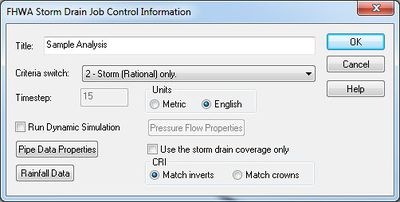
Global parameters for a storm drain analysis are defined in the Job Control dialog.
Title
The title is placed at the top of the input file to identify the model run.
Criteria Switch
Two different kinds of storm drain analysis can be performed. Option 2 is Storm only and uses the rational method (peak flow analysis) to generate the flows for the pipe network. Contributing areas, runoff coefficients, and times of concentration must be define for each storm inlet point. An intensity, duration, frequency curve must also be defined for the modeling area.
The second option is also Storm only (at this point sanitary is not an option) but uses hydrographs to define the inflow rather than the rational method analysis. In this case hydrographs can be computed from any of the models supported by WMS (i.e. HEC-1, rational, TR-55, etc.) and then mapped to the storm drain inlets.
Time Step
When running a hydrographic analysis a time step should be entered to indicate the timing for each step of the analysis.
Units
Storm drain can be run using either Metric or English units. Parameters entered should be consistent with the units specified.
Print Hydraulic Grade Line
Turn this option on to see a printout of the hydraulic grade line in the output file.
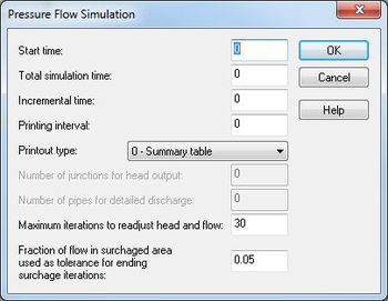
Run Pressure Flow Simulation
When running a pressure flow simulation the following properties must also be defined (see help strings for each edit field when defining for more information).
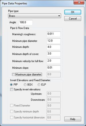
Pipe Data Properties
Default pipe properties are assigned in the Job Control dialog. If individual pipe segment properties are not defined as part of the attributes of the feature lines that make up the pipe network they will automatically inherit the properties defined here. The following dialog lists the pipe properties that must be defined.
Rainfall Data
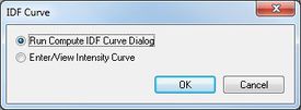
When running a rational simulation an intensity duration frequency curve must be defined for the entire area (only a single curve can be used). The Rainfall Data button allows entering manually the values defining a curve, or use the WMS IDF Curve generation dialog to set up an IDF curve for different areas of the United Stated.
Use the storm drain coverage only
A storm drain analysis is comprised of two data layers. The pipe network and the surface drainage. WMS coverages can be used to develop the parameters for both of these layers (storm drain and drainage coverages), but for some analysis it may be preferable to analyze a pipe network without having to define an entire surface drainage coverage. In this case, toggle this option on and the necessary surface drainage information can be defined from the nodes of the storm drain coverage rather than from a drainage coverage. These parameters include the area, tc, and runoff coefficients for the basins that connect to a given node in the pipe network.
Related Topics
| [hide] WMS – Watershed Modeling System | ||
|---|---|---|
| Modules: | Terrain Data • Drainage • Map • Hydrologic Modeling • River • GIS • 2D Grid • 2D Scatter |  |
| Models: | CE-QUAL-W2 • GSSHA • HEC-1 • HEC-HMS • HEC-RAS • HSPF • MODRAT • NSS • OC Hydrograph • OC Rational • Rational • River Tools • Storm Drain • SMPDBK • SWMM • TR-20 • TR-55 | |
| Toolbars: | Modules • Macros • Units • Digitize • Static Tools • Dynamic Tools • Drawing • Get Data Tools | |
| Aquaveo | ||


