GMS:Map to MODFLOW: Difference between revisions
From XMS Wiki
Jump to navigationJump to search
| (6 intermediate revisions by the same user not shown) | |||
| Line 54: | Line 54: | ||
==Automatic Layer Assignment== | ==Automatic Layer Assignment== | ||
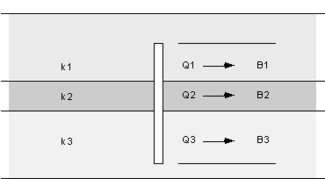
When building a MODFLOW conceptual model with a multi-layer model, it is necessary to define the range of layers associated with a particular source sink object. In the [[GMS:Coverages#Coverage_Setup|Coverage Setup]] dialog when the "Layer range" option is checked option for assigning cell properties to various layers will appear in the feature object [[GMS:Coverages#Feature_Object_Attribute_Table|Attribute Table]] under the "Auto assign layer" column including "Use layer range", "Auto-assign BC to one cell" and "Auto-assign BC including lower cells". For example, an arc corresponding to a specified head boundary condition may be associated with layers 1 | When building a MODFLOW conceptual model with a multi-layer model, it is necessary to define the range of layers associated with a particular source sink object. In the [[GMS:Coverages#Coverage_Setup|Coverage Setup]] dialog when the "Layer range" option is checked option for assigning cell properties to various layers will appear in the feature object [[GMS:Coverages#Feature_Object_Attribute_Table|Attribute Table]] under the "Auto assign layer" column including "Use layer range", "Auto-assign BC to one cell" and "Auto-assign BC including lower cells". For example, an arc corresponding to a specified head boundary condition may be associated with layers 1–3 on the edge of a model. On the other hand, a drain arc in the middle of the model may only be associated with the top layer. The following example shows how a specified head boundary condition would map with the "Use layer range" option with the range set from 1 to 2: | ||
{{hide in print|[[File:Map-layer-range.png]]}} | {{hide in print|[[File:Map-layer-range.png]]}} | ||
{{only in print|[[File:Map-layer-range.png|center|220px]]}} | {{only in print|[[File:Map-layer-range.png|center|220px]]}} | ||
In some cases, however, the proper layer for a particular source/sink object will depend on the elevation of the object relative to the layer elevations. For example, a drain may represent a channel that cuts through the terrain. In some places the channel may be shallow and correspond to layer 1. In other places, the channel may be deep enough that it cuts into layer 2. The "Auto assign to one cell" option is used for defining the layer range in these cases. If this option is selected, the object will be associated with the layer where the elevation or head associated with the object falls between the top and bottom elevation for the layer. The following shows how the same specified head boundary condition would map with the "Auto assign to one cell" option: | In some cases, however, the proper layer for a particular source/sink object will depend on the elevation of the object relative to the layer elevations. For example, a drain may represent a channel that cuts through the terrain. In some places the channel may be shallow and correspond to layer 1. In other places, the channel may be deep enough that it cuts into layer 2. The "Auto assign to one cell" option is used for defining the layer range in these cases. If this option is selected, the object will be associated with the layer where the elevation or head associated with the object falls between the top and bottom elevation for the layer. See the following table: | ||
:{|- border="1" | |||
|- | |||
!Object type !! Head or Elevation | |||
|- | |||
|Specified head condition || head stage | |||
|- | |||
|drain || bot. elev. | |||
|- | |||
|STR || bot. elev. | |||
|} | |||
The following shows how the same specified head boundary condition would map with the "Auto assign to one cell" option: | |||
{{hide in print|[[File:Map-single-cell.png]]}} | {{hide in print|[[File:Map-single-cell.png]]}} | ||
| Line 78: | Line 89: | ||
==MODFLOW-USG== | ==MODFLOW-USG== | ||
There are a few unique issues to be aware of when targeting a [[GMS:UGrid_Module|UGrid]] and [[GMS:MODFLOW-USG|MODFLOW-USG]]. The list of features below require that the UGrid be a "stacked grid". A "stacked grid" is one in which there is no vertical sub-discretization of layers and the horizontal discretization of all layers is the same (i.e. the Index of Vertical Sub-Discretization (IVSD) in the UnStructured Grid Discretization (DISU) package could be set to -1). | There are a few unique issues to be aware of when targeting a [[GMS:UGrid_Module|UGrid]] and [[GMS:MODFLOW-USG|MODFLOW-USG]]. The list of features below require that the UGrid be a "stacked grid". A "stacked grid" is one in which there is no vertical sub-discretization of layers and the horizontal discretization of all layers is the same (i.e. the Index of Vertical Sub-Discretization (IVSD) in the UnStructured Grid Discretization (DISU) package could be set to -1). It is recommended to use a stacked UGrid when possible. | ||
* Seepage face boundary condition | * Seepage face boundary condition | ||
| Line 85: | Line 96: | ||
* [[GMS:SUB_Package|SUB package]] | * [[GMS:SUB_Package|SUB package]] | ||
Also, the specified layer option is not supported by Map → MODFLOW with the RCH and EVT packages. | Also, the specified layer option is not supported by Map → MODFLOW with the RCH and EVT packages. There is a ''Specified vertical cells'' option available for the RCH package. When this option is turned on, GMS will fill the grid in with the highest active cells in each column. | ||
==See also== | ==See also== | ||


