| MODFLOW |
|---|
| Pre-processing |
|---|
|
MODFLOW Commands |
|
Building a MODFLOW Model |
|
Map to MODFLOW |
|
Calibration |
|
Packages Supported in GMS |
|
Saving a MODFLOW Simulation |
|
Importing MODFLOW Files |
|
Unsupported MODFLOW Features |
|
Run MODFLOW |
| Post-processing |
|---|
|
MODFLOW Display Options |
|
MODFLOW Post-Processing Viewing Options |
|
Reading a MODFLOW Simulation |
| Tutorials |
|---|
| Packages |
|---|
| Flow: |
BCF6, HUF, LPF, UPW |
|---|
| Solvers: |
DE4, GMG, NWT, PCG,
PCGN, LMG, SIP, SOR,
SMS |
|---|
| Other: |
BAS6, BFH, CHD1, CLN,
DRN1, DRT1, EVT1, ETS1,
GAGE, GHB1, GNC, HFB1,
HUF, LAK3, MNW1, MNW2,
OUT1, RCH1, RIV1, SFR2,
STR1, SUB1, SWI2, WEL1,
UZF1 |
|---|
|
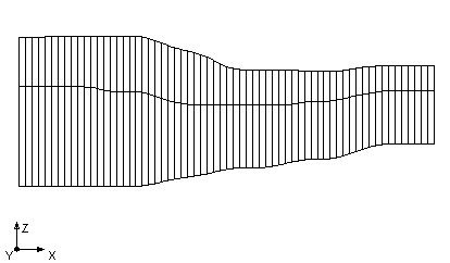
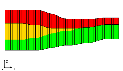
The Hydrogeologic-Unit Flow (HUF) package is an alternative to the BCF and LPF packages. It allows the user to define the vertical elevations of the hydrogeology independent of the 3D grid as shown in the figures below. Notice in the figures below that the second grid layer has more than one hydrogeologic unit associated with it.
Side view of MODFLOW grid
HUF units displayed in MODFLOW grid

The MODFLOW
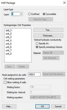
HUF Package dialog.
With the HUF package, the user then defines the top and thickness of each of the hydrogeologic units. A material is associated with each unit and the hydraulic properties (HK, VK...) are assigned to the material. The top and thickness arrays can be automatically generated from solids using the Solids → HUF command from the Solids menu or from boreholes with the Horizons → HUF command in the Boreholes menu.
Another feature in GMS that incorporates the HUF package is the ability to use TPROGS to generate HUF data.
Once the HUF package has been chosen using the Packages dialog, the HUF Package dialog can be accessed through the HUF package command in the MODFLOW menu. The following options are available in the HUF Package dialog.
Layer
This field displays the current layer. Selecting any of the input array buttons will display the corresponding layer initially. For multiple layer models, this field can be incremented or decremented to show other layers.
Layer type
This radio group selects the layer type for the current layer. By default, all layers are convertible. Only one layer type can be assigned to each grid layer.
Hydrogeologic Unit Properties
The window lists the names of the currently defined units. The Top and Thickness button bring up the MODFLOW Array Editor. For each hydrogeologic unit the user can specify if vertical hydraulic conductivity (VK) or vertical anisotropy (VANI) will be used. The material selection box shows the material assigned to the unit. The material properties (HK, VK...) are edited by selecting the Edit Materials button.
Vertical hydraulic conductivity
The HUF package has the option to enter vertical hydraulic conductivity values as either actual hydraulic conductivity values or as anisotropy factors dependant on horizontal hydraulic conductivity. These options are only available for multi-layer models.
Head Assigned to Dry Cells
This is the value that MODFLOW will give to cells with a head level below the bottom elevation of the cell (dry cell). When reading in a solution, GMS will mark cells with this value with a dry cell symbol.
Cell Rewetting Parameters
If wetting of cells is allowed, a wetting factor, wetting iteration interval, and wetting equation must be specified.


