GMS:MODFLOW Array Editor
From XMS Wiki
Jump to navigationJump to search
| MODFLOW | |
|---|---|
| Pre-processing | |
| MODFLOW Commands | |
| Building a MODFLOW Model | |
| Map to MODFLOW | |
| Calibration | |
| Packages Supported in GMS | |
| Saving a MODFLOW Simulation | |
| Importing MODFLOW Files | |
| Unsupported MODFLOW Features | |
| Run MODFLOW | |
| Post-processing | |
| MODFLOW Display Options | |
| MODFLOW Post-Processing Viewing Options | |
| Reading a MODFLOW Simulation | |
| Tutorials | |
| Packages | |
| Flow: | BCF6, HUF, LPF, UPW |
| Solvers: | SMS |
| Other: | UZF1 |
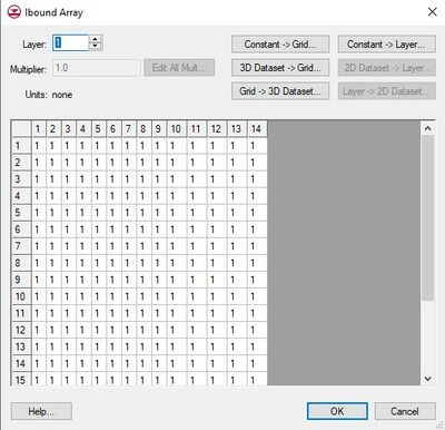
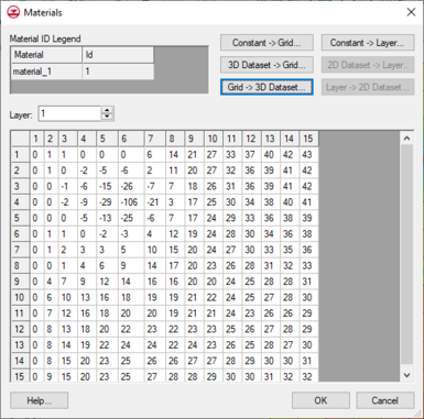
The MODFLOW Array Editor is used throughout the MODFLOW interface to edit array based data. The precise name of this dialog changes depending on which data is being accessed. The editor can include the following features:
Spreadsheet
- The array is displayed in a spreadsheet and each value can be selected and edited. Individual layers in the array are displayed one at a time. The edit fields in the spreadsheet associated with inactive cells are dimmed.
Material ID Legend
- Shown when accessing the array editor from the LPF or UPW flow package dialog. This table shows the material name and material ID. The table is populated based on the Materials properties dialog.
Layers
- The edit field in the upper left corner of the dialog is used to switch to a different layer.
Multiplier
- The Multiplier is a value that can be specified to scale all of the values in the array.
Edit All Mult
- This button brings up a spreadsheet with the multiplier for each layer in the grid.
Constant → Grid
- The Constant → Grid button prompts for a single value and assigns the value to all of the cells in the entire array.
Constant → Layer
- The Constant → Layer button prompts for a constant value which is assigned to all of the cells in the currently displayed layer.
3D Dataset → Grid
- The 3D Dataset → Grid button brings up the Select Dataset dialog listing all of the current datasets associated with the 3D grid. The selected dataset is then copied into the starting heads array. This option is typically used to load in a previously computed MODFLOW solution to use as the initial condition. The previously computed solution must be imported as a dataset before selecting this option.
2D Dataset → Layer
- The 2D Dataset → Layer button allows the user to select one of the datasets associated with a 2D grid and copy it to the current layer of the starting heads array. In order for this button to be active, a 2D grid that has the same number of rows and columns as the 3D grid must be imported or created. Such a grid can be automatically generated using the Grid → 2D Grid command in the Grid menu. The 2D Dataset → Layer option is typically used to load in a dataset that has been created by interpolating heads from a 2D scatter point set to the 2D Grid.
Grid → 3D Dataset
- The Grid → 3D Dataset button copies values from the entire starting heads array to the 3D grid dataset list.
Layer → 2D Dataset
- The Layer → 2D Dataset button copies values from the selected layer of the starting heads array to the 2D grid dataset list.
| [hide]GMS – Groundwater Modeling System | ||
|---|---|---|
| Modules: | 2D Grid • 2D Mesh • 2D Scatter Point • 3D Grid • 3D Mesh • 3D Scatter Point • Boreholes • GIS • Map • Solid • TINs • UGrids | |
| Models: | FEFLOW • FEMWATER • HydroGeoSphere • MODAEM • MODFLOW • MODPATH • mod-PATH3DU • MT3DMS • MT3D-USGS • PEST • PHT3D • RT3D • SEAM3D • SEAWAT • SEEP2D • T-PROGS • ZONEBUDGET | |
| Aquaveo | ||

