GMS:GNC Package
| This contains information about a future release of GMS. The content may not apply to other versions. |
| MODFLOW | |
|---|---|
| Pre-processing | |
| MODFLOW Commands | |
| Building a MODFLOW Model | |
| Map to MODFLOW | |
| Calibration | |
| Packages Supported in GMS | |
| Saving a MODFLOW Simulation | |
| Importing MODFLOW Files | |
| Unsupported MODFLOW Features | |
| Run MODFLOW | |
| Post-processing | |
| MODFLOW Display Options | |
| MODFLOW Post-Processing Viewing Options | |
| Reading a MODFLOW Simulation | |
| Tutorials | |
| Packages | |
| Flow: | BCF6, HUF, LPF, UPW |
| Solvers: | SMS |
| Other: | UZF1 |
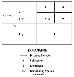
The Ghost Node Correction (GNC) package is an optional package included in MODFLOW-USG. It can be used to correct errors in the model that are created “when a line between two connected nodes does not bisect the shared face at a right angle”.[1]
GMS provides an interface to the GNC package. The package can be turned on in the MODFLOW Packages dialog, accessible from the MODFLOW Global/Basic Package dialog. The package dialog can be accessed from the main MODFLOW menu or by right-clicking on the MODFLOW item in the Project Explorer.

The user can enter the ghost node data by hand, or allow GMS to compute the data by clicking the Generate Ghost Node Data button. Clicking the button causes GMS to overwrite whatever is in the GncNodes table with the ghost node data calculated using an algorithm based on ghost node locations and distances to adjacent cells. The algorithm considers only the horizontal relationship of cells when locating ghost nodes. Thus, if the figure above is considered to be in plan view, the ghost node will be located as shown, but if it is considered to be in a front or side view with a subdivided layer on the right, no ghost node will be created.
If the Create points at ghost node locations when generating option is on, GMS will create a new UGrid called "Ghost Nodes" with points located where GMS calculated that ghost nodes should be.
GMS does not currently support some GNC package options, including:
- Parameters
- IFALPHAn (always 0 in GMS)
- Integration with the CLN (Connected Linear Network) package to correct for errors due to the CLN cells not passing through the center of the groundwater grid cell
Notes
- ^ a b Panday, Sorab, Langevin, C.D., Niswonger, R.G., Ibaraki, Motomu, and Hughes, J.D., (2013), MODFLOW-USG, version 1: An unstructured grid version of MODFLOW for simulating groundwater flow and tightly coupled processes using a control volume finite-difference formulation: U.S. Geological Survey Techniques and Methods, book 6, chap. A45, 66 p., Reston, Virginia, http://water.usgs.gov/ogw/mfusg/
| GMS – Groundwater Modeling System | ||
|---|---|---|
| Modules: | 2D Grid • 2D Mesh • 2D Scatter Point • 3D Grid • 3D Mesh • 3D Scatter Point • Boreholes • GIS • Map • Solid • TINs • UGrids | |
| Models: | FEFLOW • FEMWATER • HydroGeoSphere • MODAEM • MODFLOW • MODPATH • mod-PATH3DU • MT3DMS • MT3D-USGS • PEST • PHT3D • RT3D • SEAM3D • SEAWAT • SEEP2D • T-PROGS • ZONEBUDGET | |
| Aquaveo | ||