| MODFLOW 6 |
|---|
| Models & Tools |
|---|
GWF Model
GWT Model
Cell Properties Dialog
Zone File |
| Packages |
|---|
| Flow: |
GNC, HFB, NPF |
|---|
| GWF: |
BUY, CHD, CSUB,
DRN, EVT, GHB,
LAK, MAW, MVR,
OBS, RCH,RIV,
SFR, STO, UZF,
WEL |
|---|
| GWT: |
ADV, CNC, DSP
FMI, IC, IST, LKT,
MDT, MST, MVT,
MWT, OBS, SFT,
SRC,SSM, UZT |
|---|
| Other |
DIS, DISU, DISV,
IMS, OC, TDIS,
PEST |
|---|
|
Starting in GMS 10.5, GMS can create a basic MDOFLOW 6 project. Building a MODFLOW 6 project in GMS makes use of a simulation workflow. The new simulation workflow builds the MODFLOW 6 using a different procedure than previously used in GMS. This process allows for multiple MODFLOW 6 simulations to be contained in the same project file.
Building a MODFLOW 6 Simulation

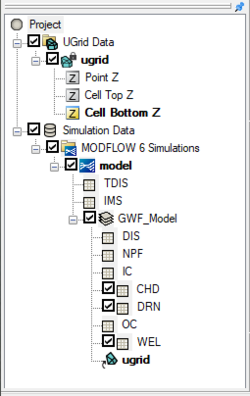
Example of a MODFLOW 6 simulation in the Project Explorer
Before building a MODFLOW 6 simulation, a 3D UGrid of the project area is required. While the project can contain multiple UGrids, only one UGrid can be attached to each MODFLOW 6 simulation.
To create a MODFLOW simulation:
- Right-click on an empty space in the Project Explorer, or right-click on "Project" in the Project Explorer, and select New Simulation | MODFLOW 6.
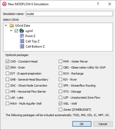
- In the New MODFLOW 6 Simulation dialog, select the UGrid for the simulation to use and select any optional packages needed for the simulation.
When the simulation has been initially created, the selected UGrid will be linked to the simulation and the simulation packages will appear in the Project Explorer. Certain packages will always be included in the simulation. These include the TDIS and IMS packages along with the GWF model which includes the DIS, NPF, IC, and OC packages. Optional packages, if any were selected, will appear under the GWF model.
Double-clicking on any of the packages listed in the Project Explorer will bring up the package dialog for that package.
In the Project Explorer, right-clicking on MODFLOW 6 simulation brings up a menu with several commands. Some of these commands are common to other Project Explorer right-click menus. Others are unique to the simulation right-click menus. Some of these unique commands are:
- "
 Simulation Data"
- Simulation Run Queue – Opens the Simulation Run Queue dialog which shows all current simulation runs.
- "
 MODFLOW 6 Simulations"
- New Simulation – Creates a new MODFLOW 6 simulation in the Project Explorer. This simulation will not contain any of the packages in any existing simulations and therefor the packages must be added. Also, creating a new simulation using this method requires linking a UGrid to the simulation.
- Simulation Run Queue – Opens the Simulation Run Queue dialog which shows all current simulation runs.
- Save All and Run – Saves all MODFLOW 6 simulations in the project and exports all files needed for the model run. It then will launch the Simulation Run Queu dialog and begin the model runs for all simulations in the project.
 Model
Model
- Simulation Run Queue – Opens the Simulation Run Queue dialog which shows all current simulation runs.
- New Package – Opens a sub-menu listing all available packages that can be added to the simulation. Selecting a package will add it to the simulation. Some packages cannot be added until certain packages have already been added to the simulation and therefore will not be available until the prerequisite package has been added.
- Model Check – Checks the simulation for model errors and brings up the Model Check dialog if any errors are found.
- Save Simulation – Saves the simulation and exports all files needed for the model run.
- Run Simulation – Starts the simulation model run and opens the Simulation Run Queue dialog.
- Save Simulation and Run – Saves the simulation and exports all files needed for the model run. It then will launch the Simulation Run Queu dialog and begin the model runs for the simulation.
- Read Solution
New MODFLOW 6 Simulation Dialog
This dialog appears when a new MODFLOW 6 simulation is first created. The dialog has the following options:
- Simulation name – A name for the simulation can be entered in this field.
- Select UGrid – This section will contain a list of available UGrids to use in the MODFLOW 6 simulation. A UGrid must be selected before the simulation can be created.
- Optional packages – This seciton contains a list of avaialble optional packages that be included when the simulation is created. A message at the bottom of this section will state which packages are already included in the simulation being created.

Example of the
New MODFLOW 6 Simulation dialog
Simulation Run Queue

Example of the
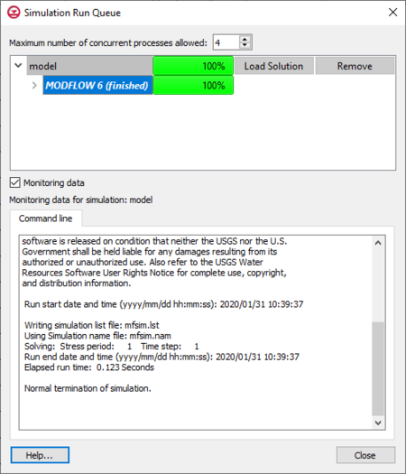
Simulation Run QueueThe Simulation Run Queue is used to manage multiple simulations. Once a simulation is started, the Simulation Run Queue appears. The dialog can also be reached by right-clicking on a simulation item in the Project Explorer and selecting the Simulation Run Queue command.
The number of processes allowed in the run queue is determined by the following option:
- Maximum Number of Concurrent Processes Allowed – Determines how many processes can be active in GMS at the same time. A simulation may contain multiple processes.
The run queue will show all simulations that are either currently running or have not yet been removed from the run queue. Each simulation will be listed in the order the simulation runs were started. Each simulation can be expanded to show what happened during the model run. If the model has a pre-processor and/or a post-processor, these will be displayed separately from the main model run. Process bars display how much of the process have been completed.
The following actions can be taken for each simulation:
- Load – Loads the solution files into SMS from a completed simulation run.
- Abort – Ends a simulation run before it has completed.
- Remove – Deletes a completed or aborted simulation from the run queue.
Towards the bottom of the dialog, the following is displayed:
- Command Line – Shows the results of the command line model run for the selected simulation.
Simulation Options Dialog
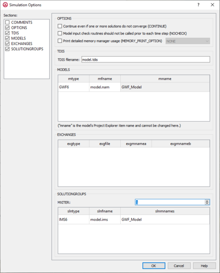
The Simulation Options dialog allows setting options that govern part of the simulation run. The dialog is reached by double-clicking on the model in the Project Explorer, or right-clicking on the model and selecting Open. The dialog has the following sections:
- Sections list – A list of sections that can be turned on or off:
- COMMENTS – Turn on to make the COMMENTS section visible.
- OPTIONS – Turn on to make the OPTIONS section visible.
- TDIS – Turn on to make the TDIS section visible.
- MODELS – Turn on to make the MODELS section visible.
- EXCHANGES – Turn on to make the EXCHANGES section visible.
- SOLUTIONSGROUPS – Turn on to make the SOLUTIONGROUPS section visible.
- COMMENTS section – Enter general alphanumeric comments. Comments entered here get written at the top of the file, preceded by a '#' symbol.
- OPTIONS – A list of options regarding actions taken concerning stored data in MODFLOW 6.
- Continue even if one or more solutions do not converge (CONTINUE) – Indicates that the simulation should continue even in the described situation.
- Model input check routines should not be called prior to each time step (NOCHECK) – Indicates that the model input check routines should not be called prior to each time step.
- Print detailed memory manager usage (MEMORY_PRINT_OPTIONS) – Controls whether the detailed memory manager usage will be printed at the end of the simulation list file.
- TDIS – Temporal Discretization Input file.
- TDIS filename – Indication of the confirmation or change in the tdis file name.
- MODELS – Model Block to be read by MODFLOW 6.
- mtype – The type of model added to a simulation.
- mfname – The file name of the model name file.
- mname – The name the user has assigned the model.
- (mname is the model’s Project Explorer name and cannot be changed here) – If the model name needs to be changed, it should be changed in the project explorer by the user.
- EXCHANGES – Exchange block to be read by MODFLOW 6.
- exgtype – The exchange type.
- exgfile – The input file for the exchange.
- exgmnamea – The name of the first model that is part of the exchange.
- exgmnameb – The name of the second model that is part of the exchange.
- SOLUTIONGROUPS – Stored solution data to be read by MODFLOW 6.
- MXITER – The area set aside to enter the maximum number of outer iterations for this solution group.
- slntype – The solution type.
- slnfname – The name of the file containing solution input.
- slnmnames – The array of model names to add to this solution.

Example of the
Simulation Options dialog for MODFLOW 6
Exporting MODFLOW 6 Files
Starting in GMS 10.4, GMS can export MODFLOW files for use with MODFLOW 6. This version of MODFLOW contains a new object-oriented program and underlying framework for supporting multiple types of models within the same simulation.
The process for doing this is similar to that of saving native text files. In the MODFLOW Global/Basic Package dialog, there is an option to Save MODFLOW 6 copy. When this option is selected, MODFLOW 6 files will be generated when running MODFLOW from GMS.
Unsupported Features
In GMS, some features of MODFLOW 6 are not yet supported or only have minimal support. These include:
- MODFLOW 6 features
- EXCHANGES in mfsim.nam file are not supported
- Only support for one SOLUTIONGROUP in the mfsim.nam file
- Multiple Groundwater Flow models
- Groundwater Flow Exchange
- Time-series files or Time-array-series files.
- GNC package
- ‘NONE’ for cellid in SFR PACKAGEDATA block is not supported
- Features in MODFLOW 6 version 6.1.0 and not in 6.0.4
- IPRN variable for arrays
- Advanced package output files
- GMS interface functionality
- Model Checker
- Conceptual model approach and Map to MODFLOW
- Observations coverage
- Cell properties for array-based RCH and EVT packages
The MODFLOW 6 export option does not function with projects that are incompatible with MODFLOW 6. Projects with unsupported features or parameters will not be successfully exported.
Not all MODFLOW packages are supported in MODFLOW 6. The following table shows the correlation between MODFLOW 6 packages and packages from previous versions of MODFLOW.
| MODFLOW 6 supported packages |
Equivalent Mf2k5/USG package
|
| CHD, DRN, GHB, RIV, WEL |
CHD, DRN, GHB, RIV, WEL
|
| DIS, DISV, DISU, TDIS |
DIS, DISU
|
| EVT, RCH |
EVT, ETS, RCH
|
| GNC |
GNC
|
| IC |
BAS
|
| LAK |
LAK
|
| MAW |
MNW2
|
| NPF, STO |
BCF, HUF, LPF, UPW
|
| SFR |
SFR
|
| UZF |
UZF
|
| MVR, GWF, OBS |
Not supported
|
| Not Supported |
DRT, GAGE, MNW1, MNWI, STR, SUB, SWI, OBS, HOB, CHOB, RVOB, STOB, DROB
|
MODFLOW 6 Files
The files generated for MODFLOW 6 will appear similar to those created for other versions of MODFLOW. The *.mfn.log file will contain notes about the export and mention any items that could not be exported for MODFLOW 6.
For more details, see the MODFLOW 6 Input and Output document
External Link


