GMS:MF6 DSP Package
From XMS Wiki
| This contains information about functionality available starting at GMS version 10.6. The content may not apply to other versions. |
| MODFLOW 6 is currently in Beta release for GMS Some features and capabilities of MODFLOW 6 are still in development for GMS. |
| MODFLOW 6 | |
|---|---|
| Models & Tools | |
|
GWF Model GWT Model Cell Properties Dialog Zone File | |
| Packages | |
| Flow: | GNC, HFB, NPF |
| GWF: |
BUY, CHD, CSUB, DRN, EVT, GHB, LAK, MAW, MVR, OBS, RCH,RIV, SFR, STO, UZF, WEL |
| GWT: |
ADV, CNC, DSP FMI, IC, IST, LKT, MDT, MST, MVT, MWT, OBS, SFT, SRC,SSM, UZT |
| Other |
DIS, DISU, DISV, IMS, OC, TDIS, PEST |
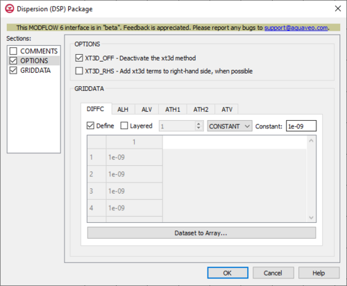
The Dispersion (DSP) Package dialog is accessed by double-clicking on the DSP package under a MODFLOW 6 simulation in the Project Explorer. It contains the following sections and options:
- Sections list – A list of sections that can be turned on or off:
- COMMENTS – Turn on to make the COMMENTS section visible.
- OPTIONS – Turn on to make the OPTIONS section visible.
- GRIDDATA – Turn on to make the GRIDDATA section visible.
- COMMENTS section – Enter general alphanumeric comments. Comments entered here get written at the top of the file, preceded by a '#' symbol.
- OPTIONS section – Options and settings:
- XT3D_OFF – This deactives the XT3D method, to use the faster but less accurate approximation method. In some circumstances, the solution this provides may be fast and accurate. These could include when flow aligns with the model grid, when there is no mechanical dispersion, or when the longitudinal and transverse dispersivities are equal. This may also be useful in assessing the computational demand of the XT3D approach, by comparing run time differences with this option turned on or off.
- XT3D_RHS – This adds XT3D terms to the right-hand side, when possible. This uses less memory, but might require more iterations.
- GRIDDATA section – This deals with the GRIDDATA block.
- Define – This allows data within the GRIDDATA section to be defined. When this is inactive in a tab, all of the options within that given tab are grayed out.
- Layered – When this is active, a numeric updown for the layers will become available.
- Drop-down and Constant/Factor – The drop-down in the GRIDDATA section has two options. The option selected will change the nature of the textbox to its right.
- "CONSTANT" – This will change the textbox to the right to be representative of "Constant". If this is selected, the spreadsheet in the GRIDDATA section will be grayed out.
- "ARRAY" – This will change the textbox to the right to be representative of "Factor". If this is selected, the spreadsheet in the GRIDDATA section will not be grayed out, and its cells will be editable.
- Dataset to Array... – This button brings up a Select Dataset dialog, where a single dataset can be selected for use in the GRIDDATA section. This will populate its spreadsheet. This option is grayed out if Define is not turned on.
- DIFFC – The DIFFC tab represents the effective molecular diffusion coefficients.
- ALH – The ALH tab represents the longitudinal dispersivities in the horizontal direction. When flow is strictly horizontal, these are the longitudinal dispersivities that will be used. When flow is neither strictly horizontal nor vertical, then the longitudinal dispersivity will be a function of both ALH and ALV. An ALH array is required when mechanical dispersion is represented (by specifying any dispersivity values).
- ALV – The ALV tab represents the longitudinal dispersivities in the vertical direction. When flow is strictly vertical, these are the longitudinal dispersivities that will be used. When flow is neither strictly horizontal nor vertical, then the longitudinal dispersivity will be a function of both ALH and ALV. An ALV array will be set set equal to an ALH array when its value is not specified and mechanical dispersion is represented.
- ATH1 – The ATH1 tab represents the transverse dispersivities in the horizontal direction. These are the transverse dispersivity values for the second ellipsoid axis. When flow is strictly horizontal and directed in the X direction (along a row for a regular grid), then these values control spreading in the Y direction. An ATH1 array is required when mechanical dispersion is represented (by specifying any dispersivity values).
- ATH2 – The ATH2 tab represents the transverse dispersivities in the horizontal direction. These are the transverse dispersivity values for the third ellipsoid axis. When flow is strictly horizontal and directed in the X direction (along a row for a regular grid), then these values control spreading in the Z direction. An ATH2 array will be set equal to an ATH1 array when its value is not specified and mechanical dispersion is represented.
- ATV – The ATV tab represents the transverse dispersivities when the flow is in the vertical direction. When flow is strictly vertical and directed in the Z direction, then these values control spreading in the X and Y directions. An ATV array will be set equal to an ATH2 array when its value is not specified and mechanical dispersion is represented.
Related Topics
| GMS – Groundwater Modeling System | ||
|---|---|---|
| Modules: | 2D Grid • 2D Mesh • 2D Scatter Point • 3D Grid • 3D Mesh • 3D Scatter Point • Boreholes • GIS • Map • Solid • TINs • UGrids | |
| Models: | FEFLOW • FEMWATER • HydroGeoSphere • MODAEM • MODFLOW • MODPATH • mod-PATH3DU • MT3DMS • MT3D-USGS • PEST • PHT3D • RT3D • SEAM3D • SEAWAT • SEEP2D • T-PROGS • ZONEBUDGET | |
| Aquaveo | ||
