GMS:MODFLOW Conceptual Model Approach: Difference between revisions
From XMS Wiki
Jump to navigationJump to search
(→Definition: added common BC initialism) |
|||
| (2 intermediate revisions by the same user not shown) | |||
| Line 14: | Line 14: | ||
== Steps in Developing a Conceptual Model == | == Steps in Developing a Conceptual Model == | ||
Several steps are involved in setting up a MODFLOW conceptual model and converting the conceptual model to a numerical model. The basic steps are as follows: | Several steps are involved in setting up a MODFLOW conceptual model and converting the conceptual model to a numerical model. The basic steps are as follows: | ||
#Create a MODFLOW conceptual model in the Map | #Create a MODFLOW conceptual model in the Map module. | ||
#Decide how many coverages are needed and what attributes are wanted with each. It is typical to use three coverages, each with a different purpose. One coverage is used for sources and sinks, like wells, specified head boundaries etc. Another coverage is used for recharge, and another is used for hydraulic conductivity. However, it is not required to use coverages in this manner, and the attributes associated with a coverage are user defined, so define a coverage with any combination of attributes. Thus, if the recharge zones were the same as the hydraulic conductivity zones, it is possible to use just one coverage for both. | #Decide how many coverages are needed and what attributes are wanted with each. It is typical to use three coverages, each with a different purpose. One coverage is used for sources and sinks, like wells, specified head boundaries etc. Another coverage is used for recharge, and another is used for hydraulic conductivity. However, it is not required to use coverages in this manner, and the attributes associated with a coverage are user defined, so define a coverage with any combination of attributes. Thus, if the recharge zones were the same as the hydraulic conductivity zones, it is possible to use just one coverage for both. | ||
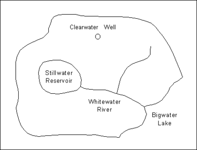
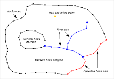
#Create the sources and sinks. The most effective way to do this is with the aid of a background [[GMS:Images|Image]]. A digital image representing a scanned map or an aerial photo of the site can be imported and displayed in the background using the image tools. Once the image is displayed, [[GMS:Feature Objects|feature objects]] defining the model boundary, rivers, lakes, flow barriers, and specified head boundaries can be created on top of the background image. | #Create the sources and sinks. The most effective way to do this is with the aid of a background [[GMS:Images|Image]]. A digital image representing a scanned map or an aerial photo of the site can be imported and displayed in the background using the image tools. Once the image is displayed, [[GMS:Feature Objects|feature objects]] defining the model boundary, rivers, lakes, flow barriers, and specified head boundaries can be created on top of the background image. | ||
| Line 24: | Line 24: | ||
#Initialize the MODFLOW data by selecting the '''New Simulation''' command in the ''MODFLOW'' menu. Select the type of mode (steady state vs. transient) and define [[GMS:Stress Periods|stress periods]] if necessary. Define a set of starting heads. Go to the ''LPF/BCF/HUF Package'' dialog and define the layer type for each of the layers in the grid. | #Initialize the MODFLOW data by selecting the '''New Simulation''' command in the ''MODFLOW'' menu. Select the type of mode (steady state vs. transient) and define [[GMS:Stress Periods|stress periods]] if necessary. Define a set of starting heads. Go to the ''LPF/BCF/HUF Package'' dialog and define the layer type for each of the layers in the grid. | ||
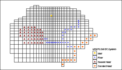
#Select the [[GMS:Map to MODFLOW|'''Map → MODFLOW''']] command to automatically assign the MODFLOW boundary conditions, stresses, and material properties to the appropriate cells in the grid. | #Select the [[GMS:Map to MODFLOW|'''Map → MODFLOW''']] command to automatically assign the MODFLOW boundary conditions, stresses, and material properties to the appropriate cells in the grid. | ||
#Use the [[GMS:Defining | #Use the [[GMS:Defining Layer Elevations|specialized interpolation]] tools to define the layer elevations. | ||
In many cases, it is useful to repeat some, but not all, of these steps. For example, suppose after running a simulation it is determined that one of the boundaries of the model corresponding to a groundwater divide is not properly located. The boundary can be moved by simply selecting and dragging the vertices and nodes of the arc(s) defining the boundary. Once the boundary is moved, step 6 should be repeated to redefine the active/inactive regions and then step 8 is repeated to reassign the model data to the cells. | In many cases, it is useful to repeat some, but not all, of these steps. For example, suppose after running a simulation it is determined that one of the boundaries of the model corresponding to a groundwater divide is not properly located. The boundary can be moved by simply selecting and dragging the vertices and nodes of the arc(s) defining the boundary. Once the boundary is moved, step 6 should be repeated to redefine the active/inactive regions and then step 8 is repeated to reassign the model data to the cells. | ||
| Line 50: | Line 50: | ||
== Defining the Layer Data == | == Defining the Layer Data == | ||
An important part of a MODFLOW model is the definition of the layer data (hydraulic conductivity, layer elevations, leakance, etc.). While both the [[GMS:3D Grid Module|Grid]] and [[GMS:Map Module|Map]] module approaches to constructing a MODFLOW model can be used to define the layer data, both approaches may lead to an overly simplistic definition of the stratigraphy. Layers with spatially varying thicknesses can be handled most effectively using a [[GMS:Defining | An important part of a MODFLOW model is the definition of the layer data (hydraulic conductivity, layer elevations, leakance, etc.). While both the [[GMS:3D Grid Module|Grid]] and [[GMS:Map Module|Map]] module approaches to constructing a MODFLOW model can be used to define the layer data, both approaches may lead to an overly simplistic definition of the stratigraphy. Layers with spatially varying thicknesses can be handled most effectively using a [[GMS:Defining Layer Elevations|special set of layer data tools]] provided in GMS. Solids can also be used to define layer data with the [[GMS:Solids to MODFLOW Command|'''Solids→MODFLOW''']] and [[GMS:Solids to HUF|'''Solids→HUF''']] commands. | ||
==See | ==See Also== | ||
*[[GMS:Map to MODFLOW|Map to MODFLOW]] | *[[GMS:Map to MODFLOW|Map to MODFLOW]] | ||
*[[GMS:Conductance|Conductance]] | *[[GMS:Conductance|Conductance]] | ||


