WMS:GSSHA Embankment Arcs
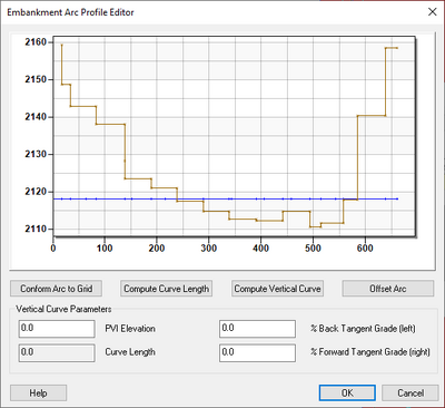
In WMS, man-made embankments are represented as embankment arcs. These embankment arcs are placed along the centerline of the actual embankment. These embankment arcs often represent roads that cross a drainage. The embankment arc can intersect a stream arc and an in-stream hydraulic structure (a culvert) placed at the intersection to allow water to pass through. For the embankment arc to function correctly in GSSHA, the elevations along the top of the arc must be defined. This is done through the Embankment Arc Profile Editor dialog.
These feature arcs are then mapped to the nearest cell edge. The embankment acts as a wall all along the edge, interrupting flow between the two adjacent cells.The wall elevation at each cell is determined by interpolation along the embankment arc. Once the water elevation has risen to this elevation, water will commence flowing over the embankment in a horizontal broad-crested weir fashion.
Embankment Arc Profile Editor Dialog
In the Embankment Arc Profile Editor dialog, the arc elevations can be generated by entering the parameters for a vertical curve. WMS will then take the given parameters and compute the correct elevation values for each vertex of the arc. The parameters needed for the vertical curve are the elevation of the point of vertical intercept, the left (back) tangent slope, the right (forward) tangent slope, and the curve length. Note that the arc need not be a straight line in plan view for the vertical curve to be computed.
The dialog is accessed through the following steps:
- Select Feature Objects | Attributes... to bring up the Properties dialog.
- Select "All" from the Show drop-down.
- Find the row for the embankment arc, making sure "Embankment" is slected from the drop=down in the Type column.
- Click
 in the Embankment column to bring up the Embankment Arc Profile Editor dialog.
The Embankment Arc Profile Editor dialog has the following features:
- At the top is a plot showing the embankment arc and an arc showing the grid elevations (default colors are blue and tan, respectively). Plot settings can be changed by double-clicking on the plot to bring up the Customization... dialog.
- Conform Arc to Grid – Sets the elevations of the arc to the corresponding grid elevations
- Compute Curve Length – Computes the length of the curve and populates the Curve Length field in the Vertical Curve Parameters section.
- Compute Vertical Curve –
- Offset Arc – Brings up the Stream offset dialog.
- Vertical Curve Parameters section
- PVI Elevation – A decimal number.
- Curve Length – Not directly user editable. Clicking Compute Curve Length or Compute Vertical Curve will populate this field with a calculated curve length.
- % Back Tangent Grade (left) – A decimal number.
- % Forward Tangent Grade (right) – A decimal number.
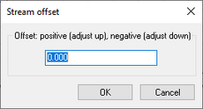
Stream Offset
The Stream offset dialog is accessible in the following ways:
- Click the Offset Arc button in the Embankment Arc Profile Editor dialog.
- In the Offset: positive (adjust up), negative (adjust down) section, enter a positive or negative decimal number by which all arc elevations will be offset. A positive number will offset the embankment curve to a location above the grid. A negative number will offset it to a location below the grid.
- Click the Offset Stream Elevations by Constant button in the Smooth GSSHA Streams dialog.
- This value offsets all of the stream bed elevations. Positive offset values lower the elevation. Surface elevations cannot be higher than the cell surface elevations. The cell surface elevations are shown in a step-wise fashion along with the stream bed profile. If the cell elevations are not visible, the most likely cause is that the stream bed elevations are too close to the cell surface elevations so that the points and lines representing the stream bed profile are drawn on top of the cell surface elevations.
At the bottom of the dialog are the following buttons:
- OK – Saves all changes and closes the Stream offset dialog.
- Cancel – Discards all changes and closes the Stream offset dialog.
GSSHA | |
|---|---|
| XMS Wiki Links | Calibration (Automated • Manual • Output) • Channel Routing • Contaminants • Digital Dams • Embankment Arcs • Feature Objects (Arcs • Nodes • Polygons) • File Types • Groundwater • Groups • Hydraulic Structures • Job Control • Join SSURGO Data • Mapping Tables • Maps • Menu • Model Linkage • Multiple Simulations • Nutrients • Observations • Output Control • Overland Soil Erosion • Pipe and Node Parameters • Precipitation • Radar Rainfall • Save GSSHA Project File • Smooth GSSHA Streams • Snowmelt • Solution (Analysis • Data) |
| Related Tools | MWBM Wizard • Using Soil Type Data with GSSHA |
| GSSHA Wiki External Links | GSSHA Wiki: Overview • Primer • User's Manual • Tutorials |
WMS – Watershed Modeling System | ||
|---|---|---|
| Modules: | Terrain Data • Drainage • Map • Hydrologic Modeling • River • GIS • 2D Grid • 2D Scatter |  |
| Models: | CE-QUAL-W2 • GSSHA • HEC-1 • HEC-HMS • HEC-RAS • HSPF • MODRAT • NSS • OC Hydrograph • OC Rational • Rational • River Tools • Storm Drain • SMPDBK • SWMM • TR-20 • TR-55 | |
| Toolbars: | Modules • Macros • Units • Digitize • Static Tools • Dynamic Tools • Drawing • Get Data Tools | |
| Aquaveo | ||

