WMS:GSSHA Feature Polygons
Feature polygons in GSSHA can be used to simulate lakes and wetland areas. In general, lakes and detention basins should be defined at a point by defining a detention basin hydraulic structure at a point attribute on a stream in a GSSHA coverage. Wetlands should generally be created as feature polygons in a GSSHA coverage.
By attenuating and storing the incoming flow, lakes and wetlands prove to be important hydrologic features of a basin and dramatically alter the response of a watershed to a precipitation event. Both in-stream and out-of-stream lakes and wetland areas can be simulated in this way. Lake and wetland polygons are conceptually modeled in WMS in the GSSHA coverage.
Lakes and wetlands must be used in conjunction with a rating curve (or other curve or hydraulic structure, if applicable) at the outlet to describe how they release the stored water. The rating curve is set up as a hydraulic structure at the outlet node of the lake or wetland.
After assigning a detention basin as a node attribute in a GSSHA coverage, the following should be done:
- Create an embankment arc downstream from the lake that represents the dam elevation for the lake. Make sure the type of arc is set to "Embankment" and that the elevations of the arc are set in the Embankment Arc Profile Editor dialog. When creating the embankment arc, the grid edges defined by the embankment arc must be downstream from the outlet point/detention basin hydraulic structure. If the edges are not downstream from the outlet (display the edges to make sure they are outside), an error will appear after defining the lake water surface elevations.
- Go to the detention basin node hydraulic structure attributes and set the minimum water surface elevation, initial water surface elevation, and maximum water surface elevation in the GSSHA Hydraulic Structures dialog.
- Define any outlet structures—such as culverts, weirs, rating curves, scheduled discharges, or rule curves—for this feature node with the detention basin attributes.
Wetlands

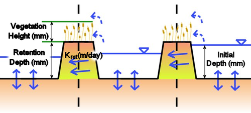
The wetland areas are treated as simple flow storage areas with special sediment conditions. The wetland sediments are treated as a lens that must be saturated before it will release water into the groundwater domain. Thus, five parameters must be specified for the wetlands area: maximum storage depth, retention depth (sediment lens thickness), base elevation, hydraulic conductivity of the sediment lens, and hydraulic conductivity of the soil just below the sediment lens (retention depth).
Wetlands can be created as feature polygons in a GSSHA coverage and define the cells that form part of a wetland. Wetland areas store small amounts of water and act as important aquifer recharge areas. The areal parameters are assumed to be homogeneous over the polygon. The wetlands areas will act as small lakes with slightly different infiltration parameters.
A different hydraulic conductivity value can be specified for the sediments responsible for the wetland condition if a high water table is not the principle cause of the wetlands. The wetlands and lakes do not have any special sediment trapping or contaminant removal parameters. They are simple treated as modifying the stream and overland flow processes. Lakes and wetlands may be in-stream or out-of-stream features.
Lakes
Lake polygons can be used to define cells within a grid used to simulate lakes during a GSSHA simulation. However, it is recommended to define them as hydraulic structures instead. For information on modeling lakes as hydraulic structures instead of polygons, please see the WMS:GSSHA Hydraulic Structures article.
GSSHA Polygon Attributes Dialog
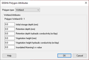
The GSSHA Polygon Attributes dialog has four different Polygon type options that can be selected from the drop-down menu. Only the "Wetland" option has user-changeable attributes.
- "Generic" – No additional attributes.
- "Boundary" – No additional attributes. Boundary polygons are used to define the perimeter of the watershed and are used for creating grids from an already known watershed boundary.
- "Wetland" – The following options are available in the Wetland Attributes section:
- Initial storage depth – Initial depth of water in the cell, from the bottom of the retention depth. A decimal value in millimeters.
- Retention depth – Depth of the peat layer. This value is actually subtracted from the elevation grid inside of GSSHA. A decimal value in millimeters.
- Retention depth hydraulic conductivity – Lateral seepage hydraulic conductivity through the peat layer. A decimal value in meters per day.
- Vegetation height – Height of the vegetation above the peat layer. A decimal value in millimeters.
- Vegetation height hydraulic conductivity – Lateral seepage hydraulic conductivity through the bottom of the vegetation. A decimal value in meters per day.
- Inundated Manning's n value – Manning's roughness value after the vegetation is overtopped (and possibly flattened.) A decimal value.
- "Depression Mask" – No additional attributes. Depression mask polygons mask cells contained within the polygon. The elevations of the cells located inside a depression mask polygon are not altered when the CleanDam program is run from WMS.
Related articles
GSSHA | |
|---|---|
| XMS Wiki Links | Calibration (Automated • Manual • Output) • Channel Routing • Contaminants • Digital Dams • Embankment Arcs • Feature Objects (Arcs • Nodes • Polygons) • File Types • Groundwater • Groups • Hydraulic Structures • Job Control • Join SSURGO Data • Mapping Tables • Maps • Menu • Model Linkage • Multiple Simulations • Nutrients • Observations • Output Control • Overland Soil Erosion • Pipe and Node Parameters • Precipitation • Radar Rainfall • Save GSSHA Project File • Smooth GSSHA Streams • Snowmelt • Solution (Analysis • Data) |
| Related Tools | MWBM Wizard • Using Soil Type Data with GSSHA |
| GSSHA Wiki External Links | GSSHA Wiki: Overview • Primer • User's Manual • Tutorials |
WMS – Watershed Modeling System | ||
|---|---|---|
| Modules: | Terrain Data • Drainage • Map • Hydrologic Modeling • River • GIS • 2D Grid • 2D Scatter |  |
| Models: | CE-QUAL-W2 • GSSHA • HEC-1 • HEC-HMS • HEC-RAS • HSPF • MODRAT • NSS • OC Hydrograph • OC Rational • Rational • River Tools • Storm Drain • SMPDBK • SWMM • TR-20 • TR-55 | |
| Toolbars: | Modules • Macros • Units • Digitize • Static Tools • Dynamic Tools • Drawing • Get Data Tools | |
| Aquaveo | ||
