WMS:MWBM Wizard
The MWBM Wizard dialog is accessed through the MWBM Wizard ![]() tool icon in the WMS Graphics Window. Mine Water Balance Modeling (MWBM) can be used to update a GSSHA model within WMS by using this dialog.
tool icon in the WMS Graphics Window. Mine Water Balance Modeling (MWBM) can be used to update a GSSHA model within WMS by using this dialog.
On the left of the dialog is a list of pages that allow modification of various parameters and data to be used in updating and running the GSSHA model. The name of the dialog changes as each page is selected from the list on the left. The pages should generally be selected and completed in the order they appear in the list.
Each of these pages is discussed and explained below.
Read Existing Model
When this page is selected, the title of the dialog is Project Filename.
The "Read Existing Model" page has one item:
- Browse for WMS project filename – Click Browse
 to bring up the Select WMS Project File dialog. Browse to the location of the desired project file.
Define Model Changes
When this page is selected, the title of the dialog is Model Changes.
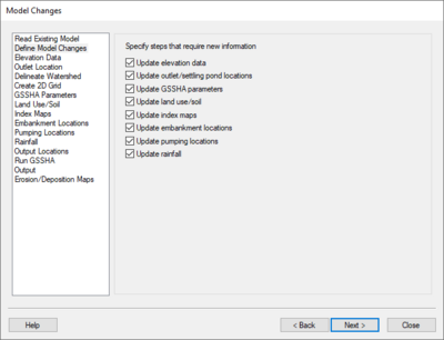
The "Define Model Changes" page allows the specification of pages in the dialog that require new information. These checkboxes allow the user to automatically skip particular pages when using the Next button if that information doesn't require updating. The user can still visit the other pages, if needed. Some options will cover more than one page.
Under Specify steps that require new information, the following options are available:
- Update elevation data – Takes the user to the "Elevation Data", "Outlet Location", "Delineate Watershed", "Create 2D Grid", and "Output Locations" pages before running GSSHA.
- Update outlet/settling pond locations – Takes user to "Outlet Locations", "Delineate Watershed", "Create 2D Grid", and "Output Locations" pages before running GSSHA.
- Update GSSHA parameters – Takes the user to the "GSSHA Parameters" and "Output Locations" pages before running GSSHA.
- Update land use/soil – Takes the user to the "Land Use/Soil" and "Output Locations" pages before running GSSHA.
- Update index maps – Takes the user to the "Index Maps" and "Output Locations" pages before running GSSHA.
- Update embankment locations – Takes the user to the "Embankment Locations" and "Output Locations" pages before running GSSHA.
- Update pumping locations – Takes the user to the "Pumping Locations" and "Output Locations" pages before running GSSHA.
- Update rainfall – Takes the user to the "Rainfall" and "Output Locations" pages before running GSSHA.
Elevation Data
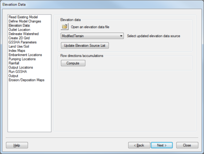
When this page is selected, the title of the dialog is Elevation Data.
This page has two sections: Elevation data and Flow directions/accumulations.
Elevation data
There are three parts to this section:
- To use elevation data different than what is already in the opened project, click Browse
 to bring up the Select DEM File(s) dialog. This allows a new DEM to be imported into the project.
 - The Select updated elevation data source drop-down contains a listing of all the available elevation data sources. Select the desired DEM from the drop-down to update the 2D grid.
- Click the Update Elevation Source List button after importing a new DEM, then select it as the desired elevation data source from the drop-down above.
Flow direction/accumulations
Clicking the Compute button computes the flow directions and accumulations for the new terrain dataset (the DEM). If the imported file has these pre-computed, it is not necessary to click this button.
Outlet Location
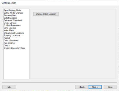
When this page is selected, the title of the dialog is Outlet Location.
This page contains a single button: Change Outlet Location. These steps must be followed by delineating the watershed.
Follow these steps to select the new outlet location:
- Click Change Outlet Location to change the cursor to a small cross-hair icon.
- In the Main Graphics Window in WMS, click on the desired new location for the outlet. The outlet must be in an flow accumulation cell; an error message will popup advising the user if the selected location is not an accumulation cell.
- If needed, use the Property section of the Main Graphics Window to manually adjust the Feature Point X and Feature Point Y locations.
Delineate Watershed
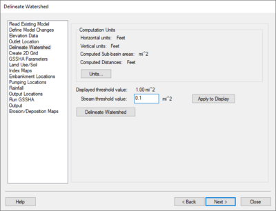
When this page is selected, the title of the dialog is Delineate Watershed.
This page has a Computation Units section, followed by a single user-adjustable option and the Delineate Watershed button.
Computation Units
This section is mostly informational, displaying horizontal and vertical units, units for the computed sub-basin areas, and units for computed distances.
- Clicking Units... brings up the Units dialog. The dialog allows model and parameter units to be set, and gives access to the drain data computation and drain data display options.
Other Options
Below the Computation Units section, four items are shown:
- Displayed threshold value – Shows the currently-displayed threshold value in the selected units.
- Stream threshold value – Allows the stream density value to be manually set. Lower values will cause the streams to be more dense while higher values will create fewer streams in the completed model.
- Apply to Display – Applies the value set in the stream threshold value field to what is displayed in the Main Graphics Window.
- Delineate Watershed – Clicking this button tells WMS to delineate the watershed using the outlet and elevation information set in previous steps.
After delineating a watershed, it is possible to manually edit the extents of the watershed.
Create 2D Grid
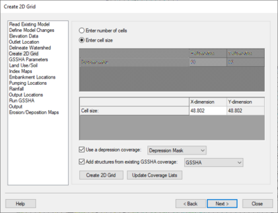
When this page is selected, the title of the dialog is Create 2D Grid.
At the top of this page are two options:
- Enter number of cells – When selected, allows the user to set the number of cells in the X-dimension. The number of cells in the Y-dimension will be adjusted automatically based on what is entered in the X-dimension field.
- Enter cell size – When selected, allows the user to enter the cell size in the X-dimension. The cell size in the Y-dimension will be adjusted automatically based on what is entered in the X-dimension field.
For the GSSHA or ModClark models to run correctly, the X and Y dimensions of the 2D grid cells must be equal.
Below the two spreadsheets are two additional options and two buttons:
- Use a depression coverage – When turned on, allows the user to select a depression coverage from a drop-down of all the appropriate coverages in the project.
- Add structures from existing GSSHA coverage – When turned on, allows the user to select from a drop-down list of all the GSSHA coverages in the project.
- Create 2D Grid – Creates a 2D grid based on the updated number of cells or cell size, the above options, the new outlet location, the delineated watershed, and elevation information.
GSSHA Parameters
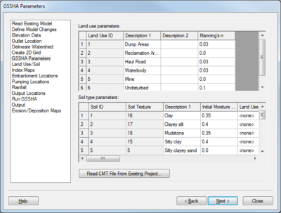
When this page is selected, the title of the dialog is GSSHA Parameters.
There are two spreadsheet sections and one button on this page:
- Land use parameters – This section lists all of the land use values within the project. The following columns are found in this spreadsheet:
- Land Use ID – Unique numeric ID for each entry. The IDs are created automatically by WMS for each entry. New land use entries can be made at the bottom of this spreadsheet.
- Description 1 – An alphanumeric description for the land use entry. User-editable.
- Description 2 – A second alphanumeric description for the land use entry. Often left blank, but can be used if further disambiguation is needed. User-editable.
- Manning's n – Roughness value used in calculating the flow through a channel. A higher value indicates a higher roughness, meaning the flow is being impeded to a certain degree. User-editable.
- Soil type parameters – This section lists all of the soil type values within the project. The following columns are found in this section:
- Soil ID – Unique numeric ID for each entry. The IDs are created automatically by WMS for each entry. New soil type entries can be made at the bottom of this spreadsheet.
- Soil Texture – A numeric soil texture value for each entry. For example, "Mudstone" might be soil texture 18, and "Silty clayey sand" might be soil texture 5.
- Description 1 – An alphanumeric description for the land use entry. User-editable.
- Initial Moisture – A value between "0.0" and "1.0". User-editable.
- Land Use ID – A drop-down populated by values from the Land use parameters spreadsheet. The default value is "<none>".
- Description 2 – A second alphanumeric description for the land use entry. Often left blank, but can be used if further disambiguation is needed. User-editable.
- Hydraulic conductivity – Ksat value in units per hour (default is cm/hr). User-editable.
- Capillary head – Head value in centimeters. User-editable.
- Porosity – Porosity value in units3/units3 (default is m3/m3). User-editable.
- Pore distribution index – Pore size distribution value in units/units (default is cm/cm). User-editable.
- Residual saturation – Residual saturation value in units3/units3 (default is m3/m3). User-editable.
- Field capacity – Specific retention value in units3/units3 (default is m3/m3). User-editable.
- Wilting point – Saturation value in the soil of the minimal amount of water that plants require to not wilt, in units3/units3 (default is m3/m3). User-editable.
- Coefficient for detachment by rainfall – Ratio of sediment detachment by rainfall, 1/J. User-editable.
- Rill erodibility coefficient – A value in seconds per meter (s/m). User-editable.
- Rill erodibility exponent – A dimensionless value. User-editable.
- Critical rill detachment – A force value in Pascals (Pa). User-editable.
- Erodibility coefficient – A dimensionless value. User-editable.
- Medium Gravel – Percentage of medium gravel in the total volume of sediment. Values of medium gravel, medium sand, medium silt, and medium clay must add up to 100. User-editable.
- Medium Sand – Percentage of medium sand in the total volume of sediment. Values of medium gravel, medium sand, medium silt, and medium clay must add up to 100. User-editable.
- Medium Silt – Percentage of medium silt in the total volume of sediment. Values of medium gravel, medium sand, medium silt, and medium clay must add up to 100. User-editable.
- Medium Clay – Percentage of medium clay in the total volume of sediment. Values of medium gravel, medium sand, medium silt, and medium clay must add up to 100. User-editable.
- Read CMT File From Existing Project... – Brings up the Open dialog where a CMT file can be selected for importing. The imported file can either overwrite the existing information or be appended to it.
Land Use/Soil
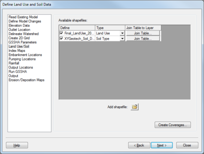
When this page is selected, the title of the dialog is Define Land Use and Soil Data.
There is one spreadsheet section and two buttons on this page:
- Available shapefiles – This section contains a spreadsheet listing all the available shapefiles in the project. There are three columns:
- Define – Contains a checkbox and the name of the shapefile. Uncheck the box to turn off a specific shapefile in the MWBM Wizard dialog. This field is not user editable.
- Type – This is a drop-down with the following options:
- "1D-Hyd Centerline"
- "1D-Hyd Cross Section"
- "Area Property"
- "CE-Qual-W2 Branch"
- "CE-Qual-W2 Segment"
- "Drainage"
- "Flood Barrier"
- "Flood Extent"
- "Floodplain Mapping"
- "General"
- "GSSHA"
- "GSSHA Storm Drain"
- "HY-8 Culvert"
- "Land Use"
- "MODRAT DPA Zone"
- "NSS Region"
- "Rain Gage"
- "Rainfall Zone"
- "Runoff Coefficient"
- "Sanitary Sewer"
- "Soil Type"
- "Storm Drain"
- "Time Computation"
- "Water Distribution"
- Join Table to Layer – Click Join Table... to bring up the Select Table File dialog. This allows the user to import a table file and join it to the selected shapefile.
- Add shapefile – Click Browse
 to bring up the Select shapefile dialog. This allows additional shapefiles to be imported into the project.
 - Create Coverages... – Clicking this button brings up the GIS to Feature Objects Wizard dialog for each selected shapefile. Go through the wizard for each shapefile in turn.
Index Maps
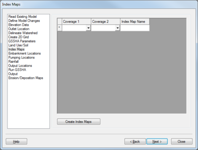
When this page is selected, the title of the dialog is Index Maps.
There is one spreadsheet section and one button on this page. The spreadsheet section has three columns:
- Coverage 1 – Required. Contains a drop-down listing all of the Land Use and Soil Type coverages. Select the desired coverage from the list.
- Coverage 2 – Optional. Contains a drop-down listing all of the Land Use and Soil Type coverages. If creating a combined index map, select a different coverage from the drop-down to act as an overlay on the coverage selected in the Coverage 1 column.
- Index Map Name – Enter the name of the index map being created.
Once all the desired index maps are specified in the spreadsheet, click Create Index Maps to create the new index map(s) and bring up the GSSHA Map Table Editor dialog.
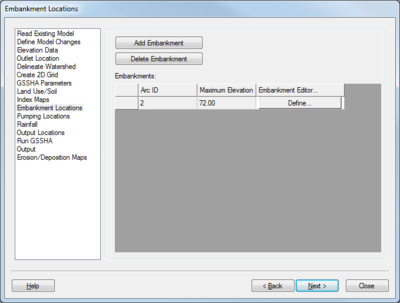
Embankment Locations
When this page is selected, the title of the dialog is Embankment Locations.
There are two buttons at the top of this page.
- Add Embankment – Enables the tool to create a GSSHA embankment arc. After clicking this button, the cursor will appear as a crosshair when in the Main Graphics Window. Click out the embankment arc where desired, then double-click to end the arc.
- Delete Embankment – Enables the tool to delete a GSSHA embankment arc. After clicking the button, click on the arc that should be deleted to immediately delete it.
Below the buttons is a spreadsheet listing of all the embankments in the project. The spreadsheet has the following columns:
- Arc ID – Displays the arc ID for each embankment. Not user editable.
- Maximum Elevation – Displays the maximum elevation of the embankment arc. Not user editable.
- Embankment Editor... – Click Define... to bring up the Embankment Arc Profile Editor dialog.
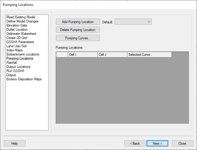
Pumping Locations
When this page is selected, the title of the dialog is Pumping Locations.
There are three buttons and a drop-down list at the top of this page:
- Add Pumping Location – Enables the tool to create a new pumping location. After clicking this button, the the cursor will appear as a crosshair when in the Main Graphics Window. Click where desired within the project 2D grid extents to create a new pumping location.
- Default – A drop-down listing of defined pumping curves. Select the desired curve to be the default for any new pumping locations. If no pumping curves are defined, the list will be blank.
- Delete Pumping Location – Enables to the tool to delete a pumping location. After clicking this button, click on the pumping location that should be deleted to immediately delete it.
- Pumping Curves... – Brings up the XY Series Editor dialog. Allows the user to manually create any number of pumping curves which will then appear in the Default list above.
- Enter the name of the curve in the Curve Name field.
- Enter starting time in the Time (min) column in the first row in the spreadsheet on the left.
- Enter the discharge rate for that time in the Discharge (cms) in the first row.
- Enter any additional times and discharge rates as desired.
- The final time should match the duration of the simulation.
Below the buttons is a spreadsheet listing of all the pumping locations in the project. The spreadsheet has the following columns:
- Cell I and Cell J – Lists the coordinates of the cell containing the pumping station.
- Selected Curve – Click Define... to bring up the XY Series Editor dialog. Select the desired curve from the Selected Curve drop-down, or do the following to create a new curve:
- Enter the name of the new curve in the Curve Name field.
- Enter starting time in the Time (min) column in the first row in the spreadsheet on the left.
- Enter the discharge rate for that time in the Discharge (cms) in the first row.
- Enter any additional times and discharge rates as desired.
- The final time should match the duration of the simulation.
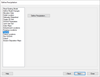
Rainfall
When this page is selected, the title of the dialog is Define Precipitation.
Click the Define Precipitation... button to bring up the GSSHA Precipitation dialog.
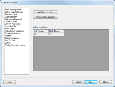
Output Locations
When this page is selected, the title of the dialog is Output Locations.
The Output Locations page allows the user to specify where GSSHA will generate a hydrograph. The following buttons appear at the top of this page:
- Add Output Location – Enables the tool to create a new GSSHA hydrograph output location. After clicking this button, the the cursor will appear as a crosshair when in the Main Graphics Window. Use the crosshair to select an existing node and enable the GSSHA hydrograph output attributes for it. Note that this will require all links and nodes in the project to be renumbered.
- Delete Output Locations – Enables the tool to remove the GSSHA hydrograph output attributes from the selected node. Clicking on a node with these attributes will immediately remove them.
The Output Locations spreadsheet lists all of the hydrograph locations currently in the project. There are two columns:
- Link Number – The link number of the output location.
- Node Number – The node number of the output location.
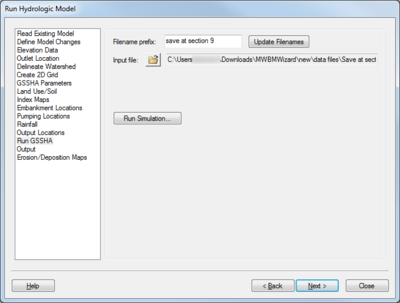
Run GSSHA
When this page is selected, the title of the dialog is Run Hydrologic Model.
This page allows the GSSHA project to be named, saved, and run.
- Filename prefix – Lists the current filename prefix for the project. All of the project files have this prefix inserted at the front of each project filename.
- Update Filenames – If the Filename prefix is changed, click this button to update all the project filenames with the new prefix.
- Input file – Click Browse
 to bring up the Select Model Input Filename dialog. The file here should be the same as that selected in the Read Existing Model step.
 - Run Simulation... – Once the above items have been verified and updated, clicking this button will launch the GSSHA Model Wrapper dialog.
- When Close is clicked in that dialog, the GSSHA Run Options dialog will come up.
- When OK is clicked, the GSSHA Model Wrapper dialog will come up and GSSHA will run.
Output
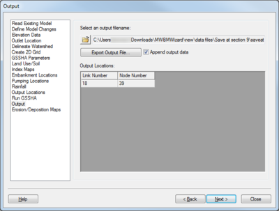
When this page is selected, the title of the dialog is Output.
The Output page allows hydrographs generated by GSSHA to be exported as comma-separated value (CSV) files.
- Select an output filename – Click Browse
 to bring up the Select a CSV Export File dialog.
 - Export Output File... – Clicking this button brings up the View Data File dialog. This dialog allows the CSV file to be opened in the desired text editor, selectable from the Open With drop-down or by clicking the Find Other... button.
- Append output data – Turning on this option will append the output to a previously-generated file (if it exists).
The Output Locations spreadsheet has two columns in it:
- Link Number – The link number of the output location.
- Node Number – The node number of the output location.
Erosion/Deposition Maps
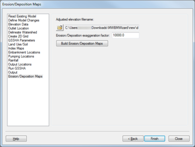
When this page is selected, the title of the dialog is Erosion/Deposition Maps.
The Erosion/Deposition Maps page allows the generation of erosion and deposition maps.
- Adjusted elevation filename – Click Browse
 to bring up the Select Adjusted Elevation Map dialog. Select the the adjusted elevation filename generated by GSSHA.
 - Erosion/Depostion exaggeration factor – This variable is used to multiply the elevation changes due to erosion and deposition on order to more easily see the changes. This is especially helpful when the changes may be very small.
- Build Erosion/Deposition Maps – Click this button to generate the erosion and deposition maps.
GSSHA | |
|---|---|
| XMS Wiki Links | Calibration (Automated • Manual • Output) • Channel Routing • Contaminants • Digital Dams • Embankment Arcs • Feature Objects (Arcs • Nodes • Polygons) • File Types • Groundwater • Groups • Hydraulic Structures • Job Control • Join SSURGO Data • Mapping Tables • Maps • Menu • Model Linkage • Multiple Simulations • Nutrients • Observations • Output Control • Overland Soil Erosion • Pipe and Node Parameters • Precipitation • Radar Rainfall • Save GSSHA Project File • Smooth GSSHA Streams • Snowmelt • Solution (Analysis • Data) |
| Related Tools | MWBM Wizard • Using Soil Type Data with GSSHA |
| GSSHA Wiki External Links | GSSHA Wiki: Overview • Primer • User's Manual • Tutorials |
WMS – Watershed Modeling System | ||
|---|---|---|
| Modules: | Terrain Data • Drainage • Map • Hydrologic Modeling • River • GIS • 2D Grid • 2D Scatter |  |
| Models: | CE-QUAL-W2 • GSSHA • HEC-1 • HEC-HMS • HEC-RAS • HSPF • MODRAT • NSS • OC Hydrograph • OC Rational • Rational • River Tools • Storm Drain • SMPDBK • SWMM • TR-20 • TR-55 | |
| Toolbars: | Modules • Macros • Units • Digitize • Static Tools • Dynamic Tools • Drawing • Get Data Tools | |
| Aquaveo | ||
